
PROBLEM
Manufacture a functioning engine powered by compressed air using given engineering drawings to be assembled and tested within 4 weeks. Ensuring manufacturing plan and risk assessments are to be completed before manufacture

SOLUTION
Before the beginning of manufacture, great care was taken into creating detailed manufacturing plans of each component of the air engine. Parts that required the use of CNC needed further calculations as part of this.
Depending on the accuracy and quality of manufacture, during testing a standard air supply was put through the engine to test its output power.
During this project, a variety manufacturing techniques were learned and confidence in this was gained. Using tri-axial CNC milling machines, CNC lathe machine and manual lathe milling machines. Great care was taken to the surface quality of the finished product to ensure any burs and sharp edges were filed down.
Using measuring equipment such as veneer calipers, micrometers and rulers to ensure the product is within tolerance throught the manufacturing process to ensure it is within the engineering drawing specifications.
Using measuring equipment such as veneer calipers, micrometers and rulers to ensure the product is within tolerance throught the manufacturing process to ensure it is within the engineering drawing specifications.
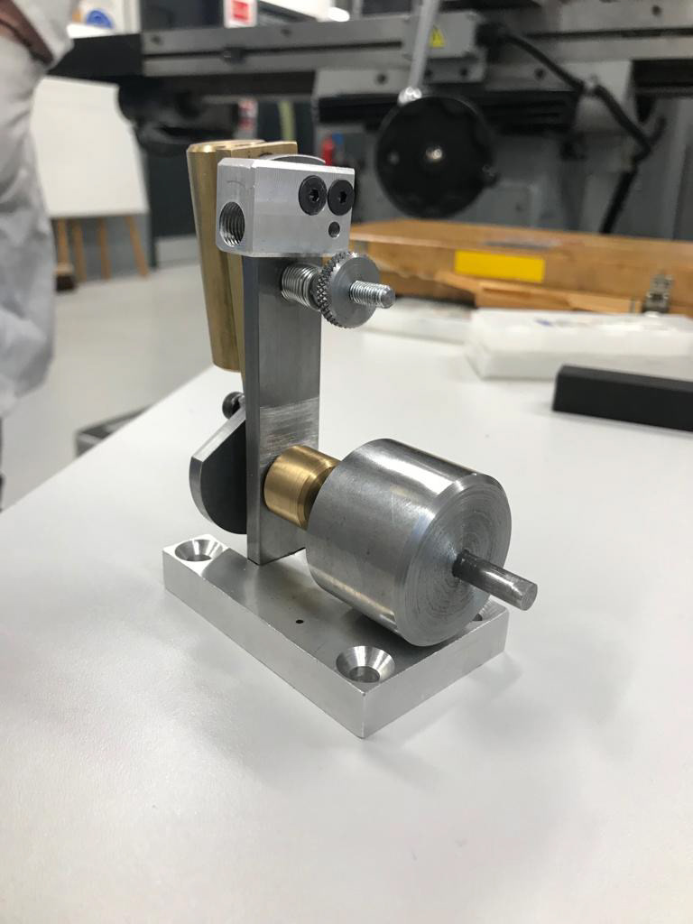
Assembled Final Air Engine

GIVEN ENGINEERING DRAWINGS
Great care was used to interpret the given engineering drawings for this project. Raw materials were given in block form, all parts had to be manufactured from scratch excluding standard screws. If tolerances in the manufacturing were incorrect this would make it difficult for the air engine to be assembled to each other.
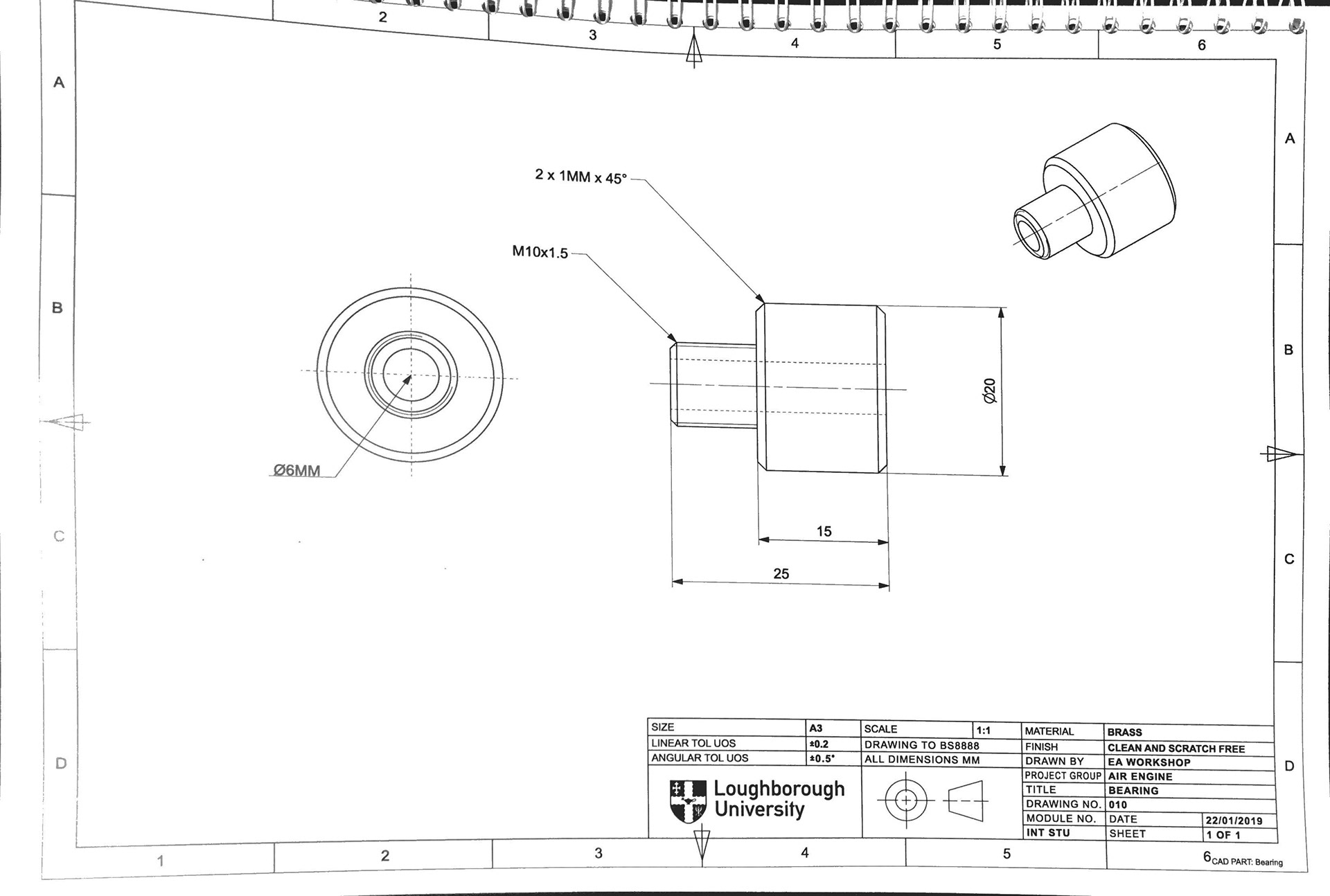
Engineering Drawing for Air Engine Bearing
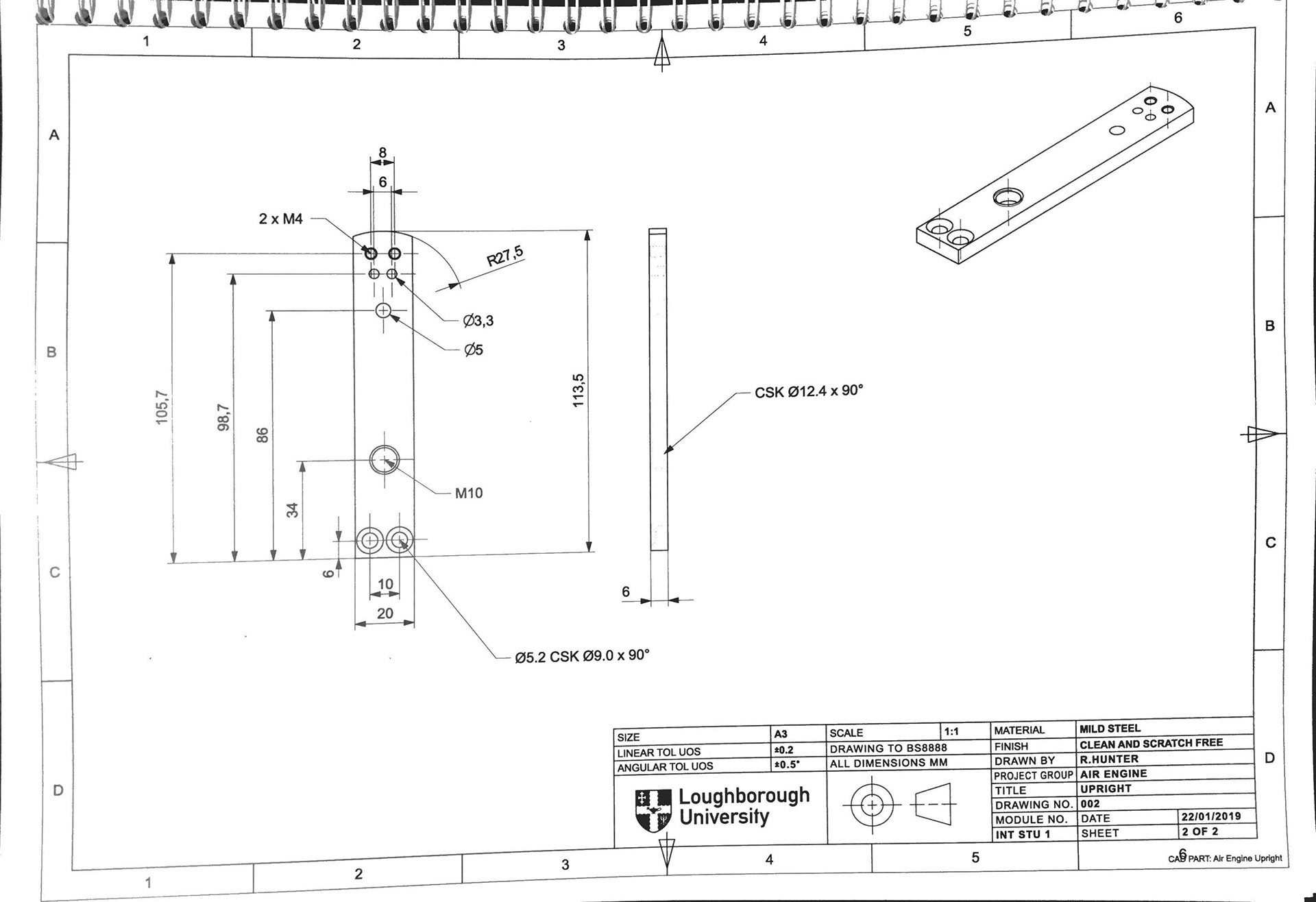
Engineering Drawing for Air Engine Connecting Part

METAL FABRICATION MANUFACTURING
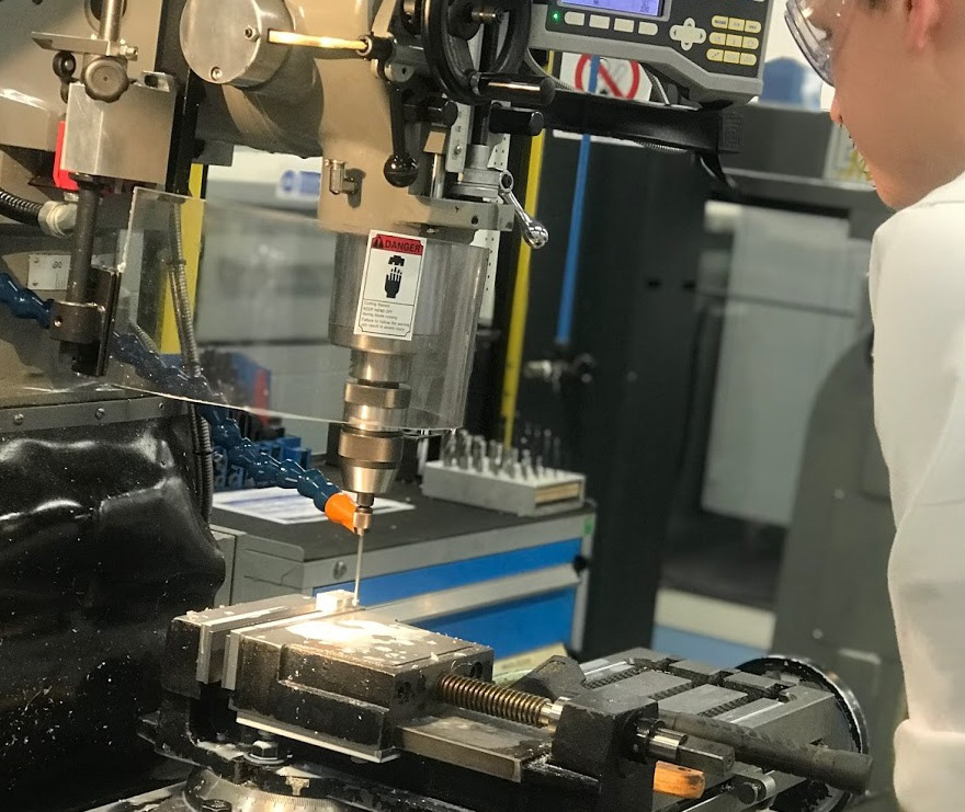
Europa 2000VS Milling Machine, manufacturing an air engine part
Great care was taken to ensure machining accuracy.
The use of the electronic interface in the milling machine gave great guidance with accuracy in the manufacturing of these components. By setting the datum, we can accurately remove material in relation to each other.
However constant measurements were taken to ensure the electronic interface were correct.
Required large amounts of focus to ensure that sufficient material was removed, as subtracting too much material could not be done. Great care was taken to ensure that the engineering drawings were interpreted accurately. It would be easy to mistake some diameters or tolerances for each other.

AIR ENGINE TESTING VIDEO
