
PROBLEM
Using mathematical modelling and knowledge of Engineering Science in Microsoft Excel to create and design a crane with 5 members and set parameters as shown in the figure on the right. Must determine the best choice is material, cross section and length with the goal of proposing a final design with a high DPI to be manufactured and tested against the mathematical model by loading weight to failure at fixed design requirements as shown in the diagram on the right.
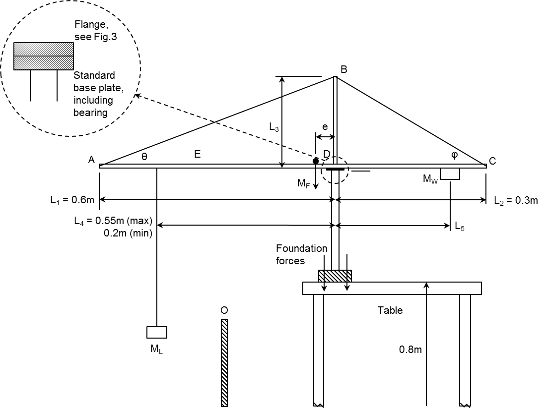
Set Design Requirements for Crane Design

SOLUTION
The final proposed design, as shown on the right, was calculating using mathematical modelling of stress and joint calculations in Microsoft Excel. Achieving the highest performance index of 83 of multiple design iterations.
Great care was taken to ensure the calculations was designed to withstand worst case scenarios during testing, e.g max loads at max distances. As well as not to be "over engineered".
The final mathematical model was designed to hold a max load of 55 kg with a counterbalance load of 45 kg at a Safety Factor of 2. During testing, the crane withstood a 90 kg load until failure.
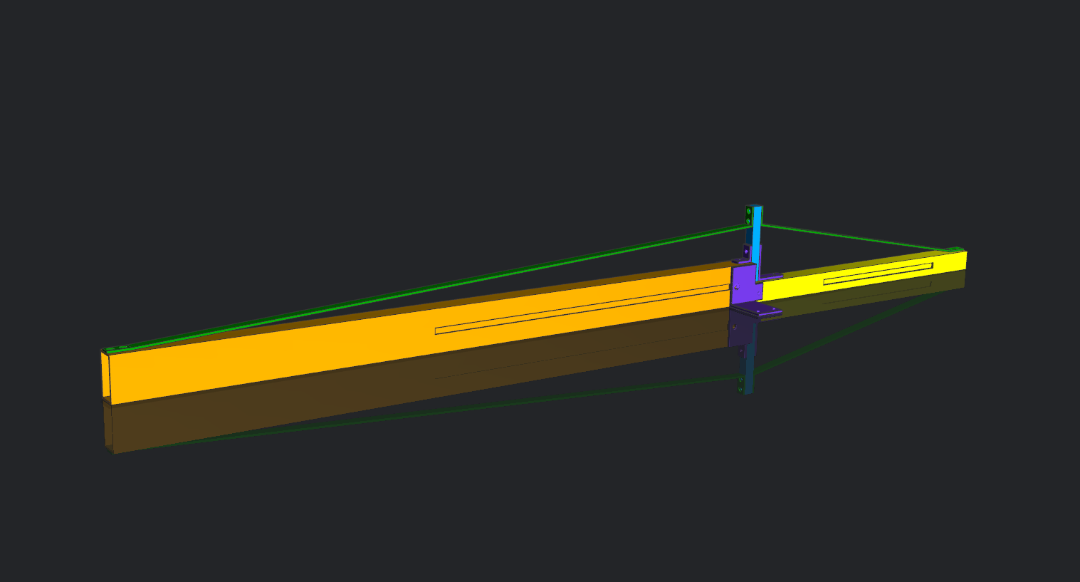
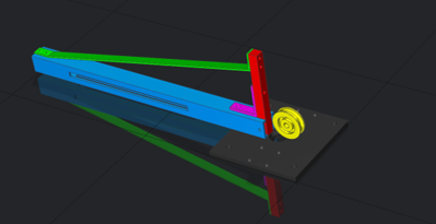
Final Crane Proposal Design CAD Model - Ready for Manufacture

MATHEMATICAL MODELLING
Snippets from calculations used in Microsoft Excel for the final design proposal.

Component Length and Forces Calculated
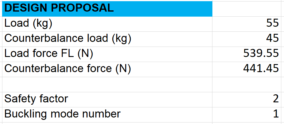
Final Design Proposal at Maximum Loads
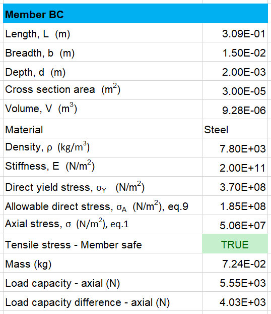
Example Calculation of Member BC
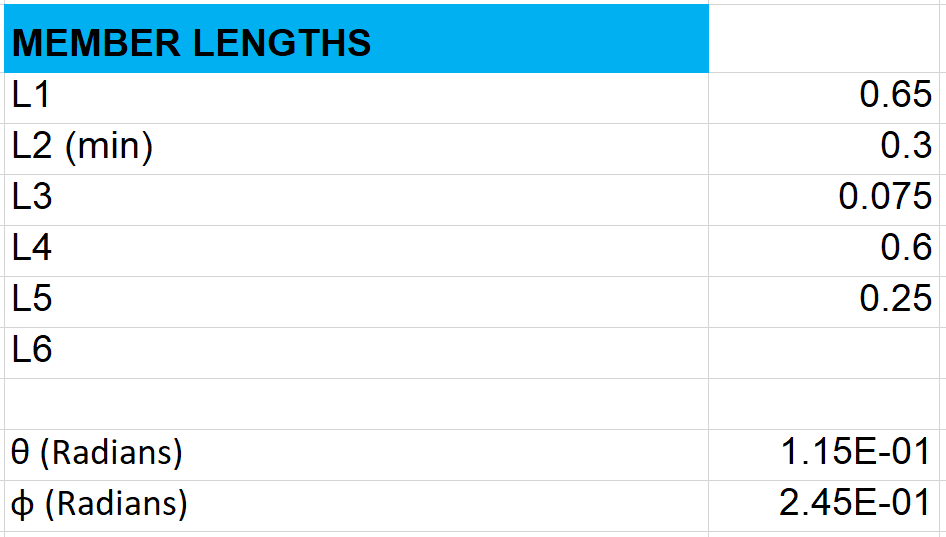
Member Lengths for Final Design Proposal
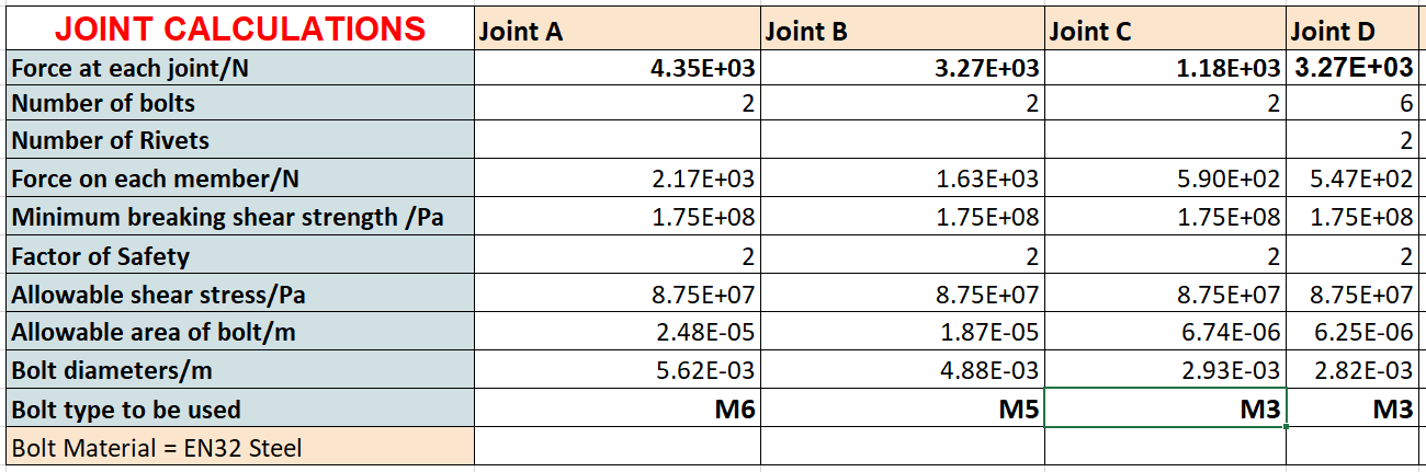
Joint Calculations in Microsoft Excel - Used to identify which bolt to use

FINAL DESIGN PROPOSAL
Produced CAD models in SIEMENS NX 11 to produce engineering drawings for manufacture.
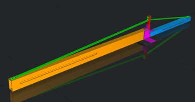
Full Body View
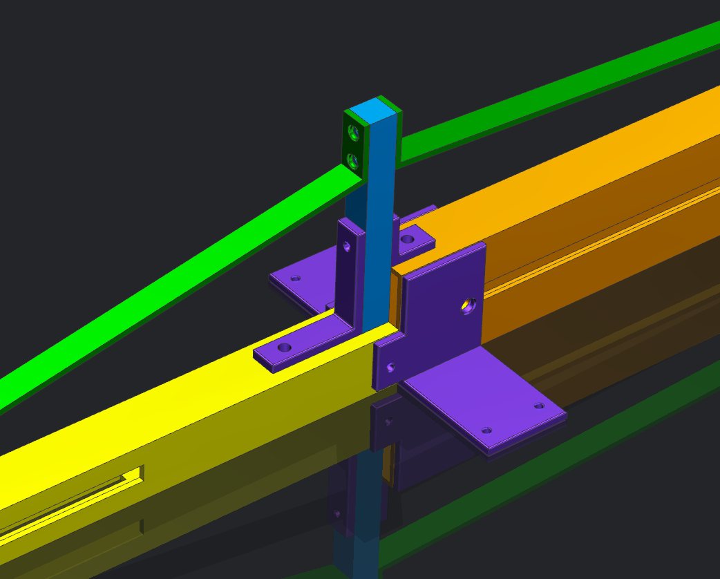
Joint View
Pully System View

MANUFACTURING
Engineering drawings and manufacturing plans were created prior to manufacturing. Using multiple metal fabrication techniques.
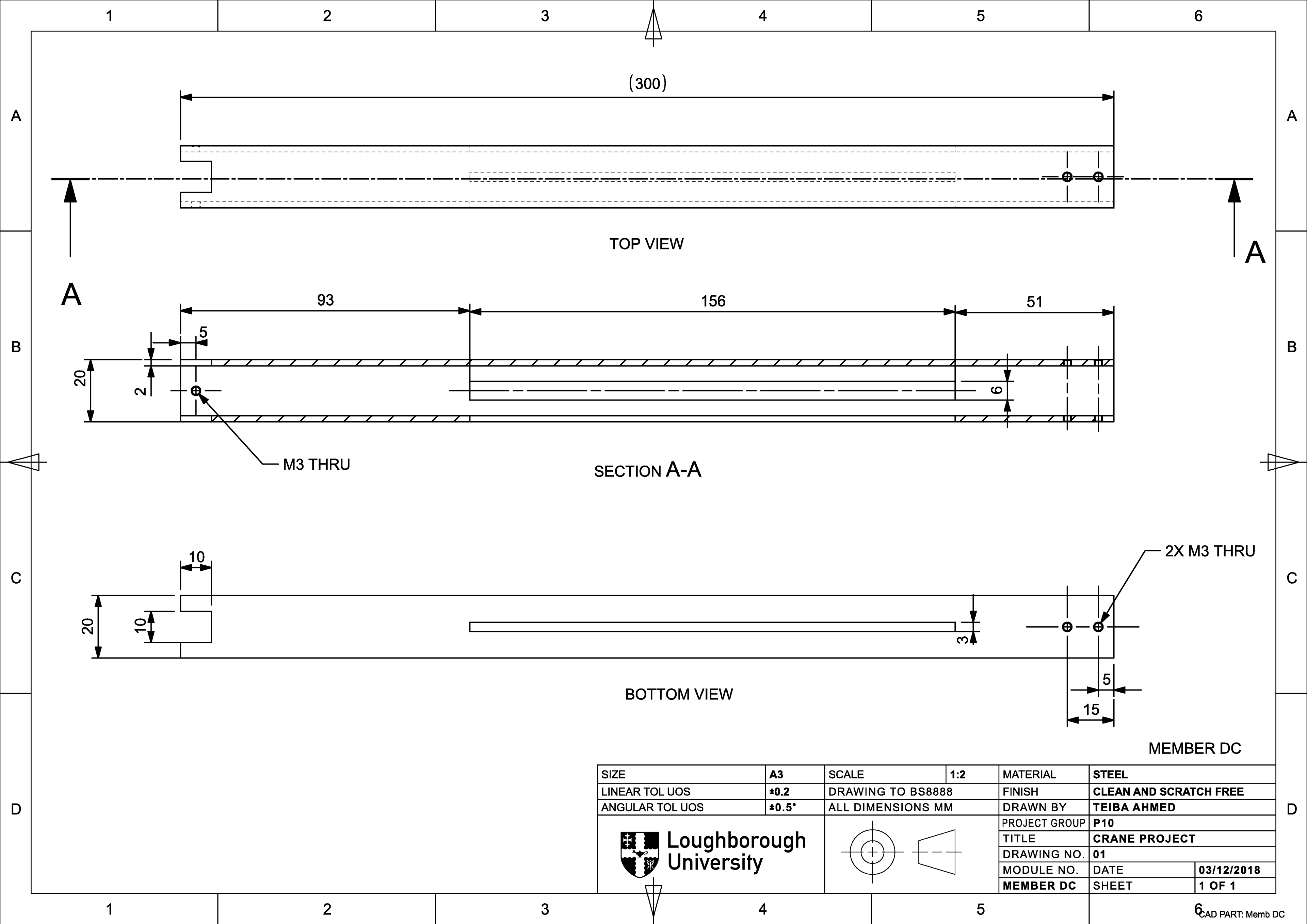
Engineering Drawing for Member DC
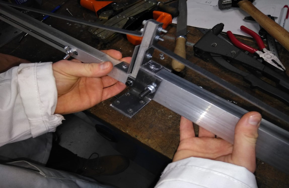
Finished Manufacture of Joints
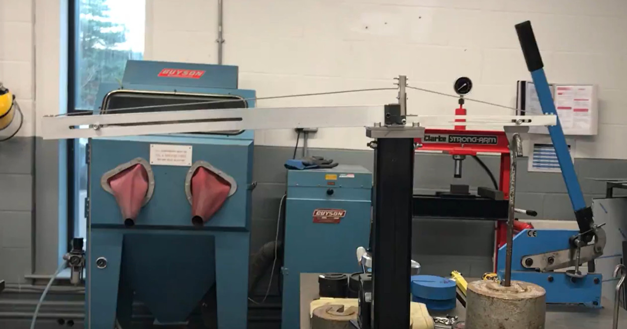
Crane Design Mounted on Testing Rig

CRANE TESTING
This video shows our crane under testing - being loaded to failure (90 kg).
With a buckling failure occurring at Member DC.
With a buckling failure occurring at Member DC.
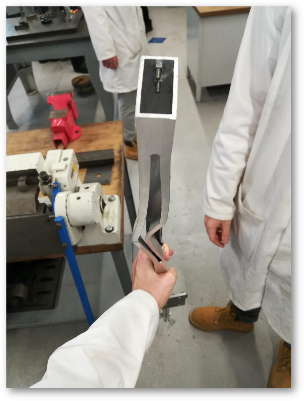
Member DC: Bucking Failure at 90 kg
